| Modifiying
the frequency range of the vibrato |
||||
| DISCLAIMER : Any modification to any MiniBrute will immediately void its warranty. Arturia or any of its affiliates will not accept responsibility for any damages, personal loss or injury that may result from any modification to the device. Should you apply any of the hacks and modifications described on this site, your own responsability alone is engaged. | ||||
Aim of the modification: The idea is to add a lever switch at
the back of the MiniBrute that makes it possible to
toggle between the normal vibrato range and an extended
audio range. With the audio range the vibrato turns into
a FM modulator for the main oscillator. With this one
can create bell sounds and other crazy FM modulations.
Difficulty : For experienced DIYers. Requires a good experience in soldering and drilling. |
||||
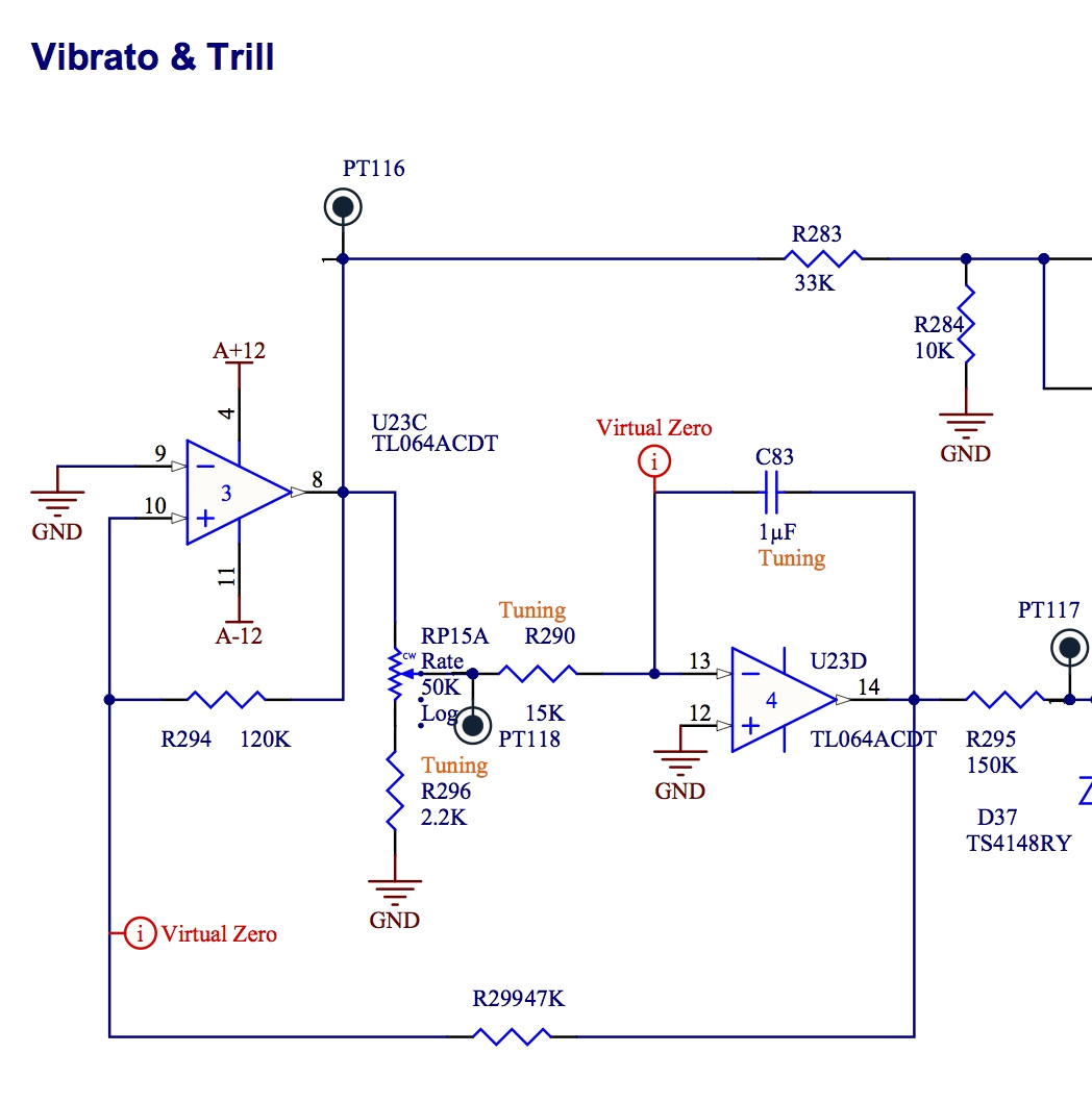
| Principle of the
modification |
||||
Required parts : two 33cm (13") long wires, one 1µF non polarized capacitor, one 33nF capacitor, one mini lever switch SPDT. A euro-cent coin gives the scale. And a small length of shrink tubing. 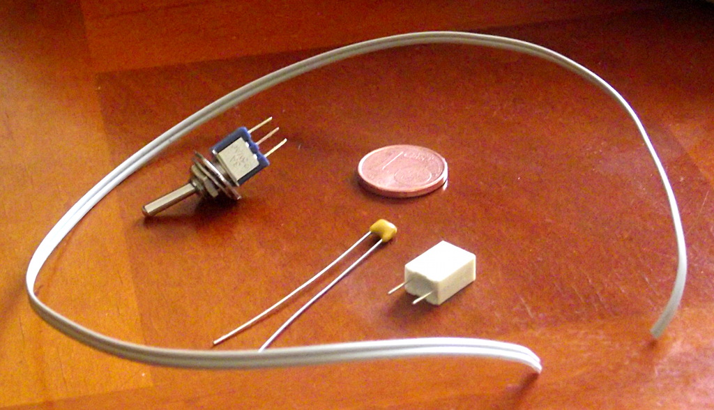 |
||||
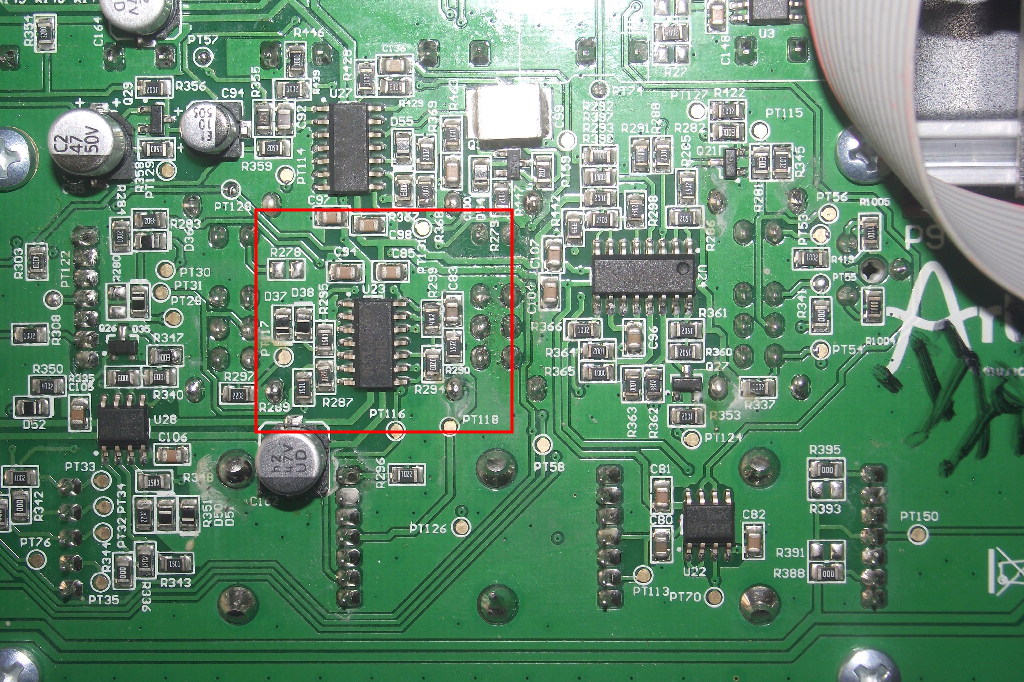
| Finding the Vibrato
on the PCB |
||||
  |
||||
| Mechanical
part: drilling the MiniBrute's case |
||||
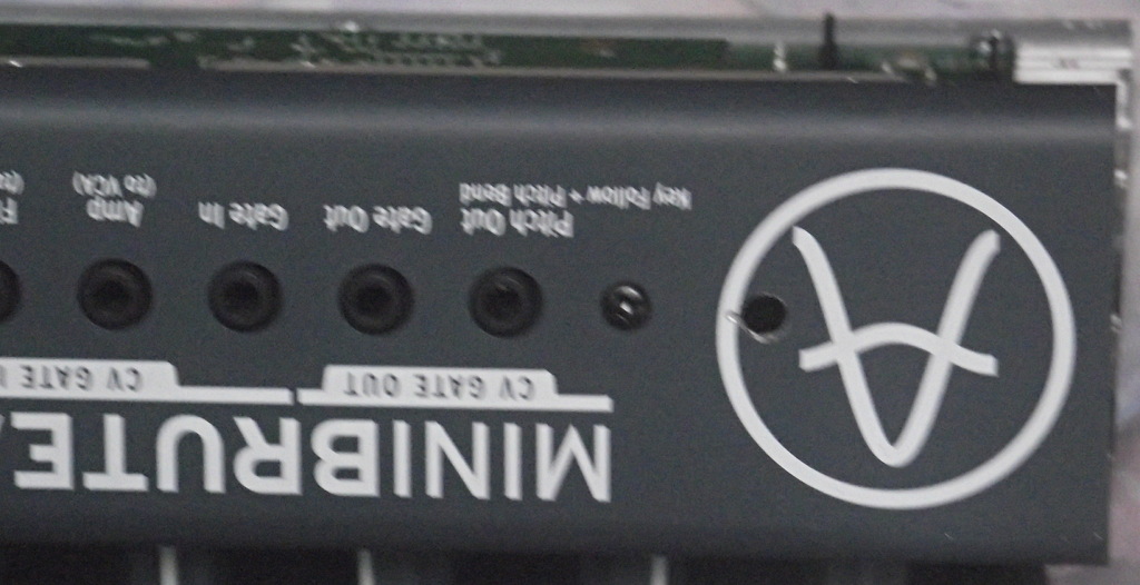
Let's find a place on the back of the case. The only place with room left for drilling and installing a switch is located at the level of the Arturia's logo. 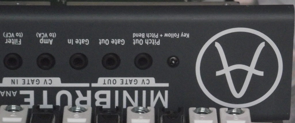 Let's stick a piece of paper tape on
the region to be drilled at the back of the case and
also inside the case. The tapes protect the paint from
small scratches that may occur when positionning the the
drill. It is also used to draw a mark (cross) for
drilling.
 A 5 mm hole is required, but in
order to be accurate I first used a 2 mm drill bit to
make the pilot hole then a 5 mm bit to make the final
hole. Note that the aluminum of the case is quite easy
to drill through and I recommend using a rather low
speed for the driller.
 The mini-lever switch fits perfectly at the back of the case... 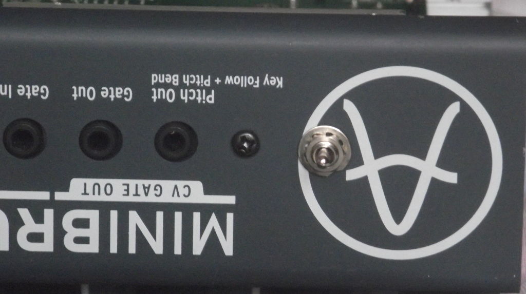 ... and is fairly accessible from the inside of the MiniBrute. 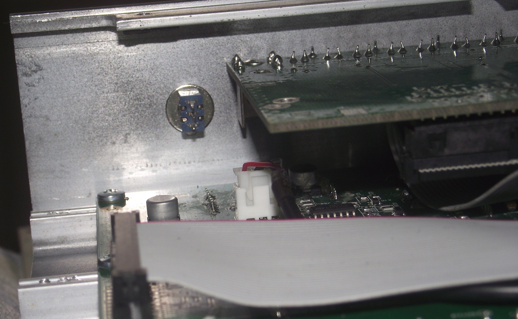 |
||||
| Electronic part:
assembly and connections |
||||
Solder one of the wire to the middle
lug of the switch. Protect the connection with shrink
tubing (white tubing on the photo below).
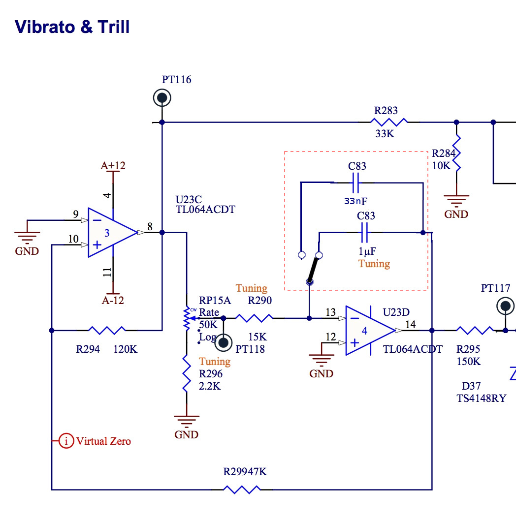
Solder one leg of the 1µF capacitor to one of the external lugs of the switch. Solder one leg of the 33nF capacitor to the other external lug. Next solder the free legs of the capacitors together. And finally solder the second wire to the connection between the two capacitors. 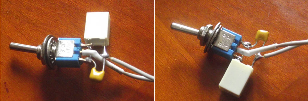 Install the switch on the back of the
MiniBrute.
 Now comes the hard part we must unsolder C83 from the PCB, as it is a SMD component we must use a small tip solder iron. . Locate C83 on the PCB (brown component). Unsolder C83. One must be careful not to overheat the soldering pads 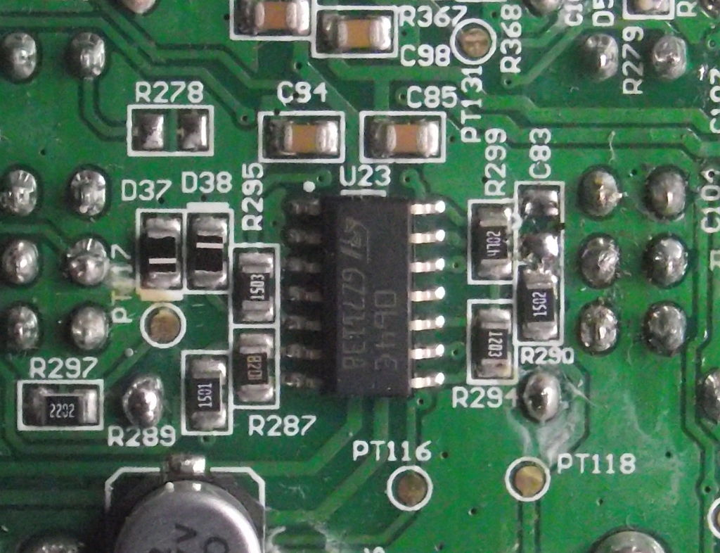 Now solder the two wires on the solder pads of the former C83 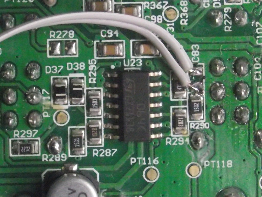 That's it, now let's re-assemble the MiniBrute and enjoy this new feature. |